
A crew installs a listed rail system with integrated grounding clips that pierce anodizing to bond modules to rails, plus a copper lug for the equipment ground wire. The inspector wants continuous fault path with no field improvising. Which grounding method best uses listed bonding components?
Select an answer to reveal the explanation.
Short Explanation
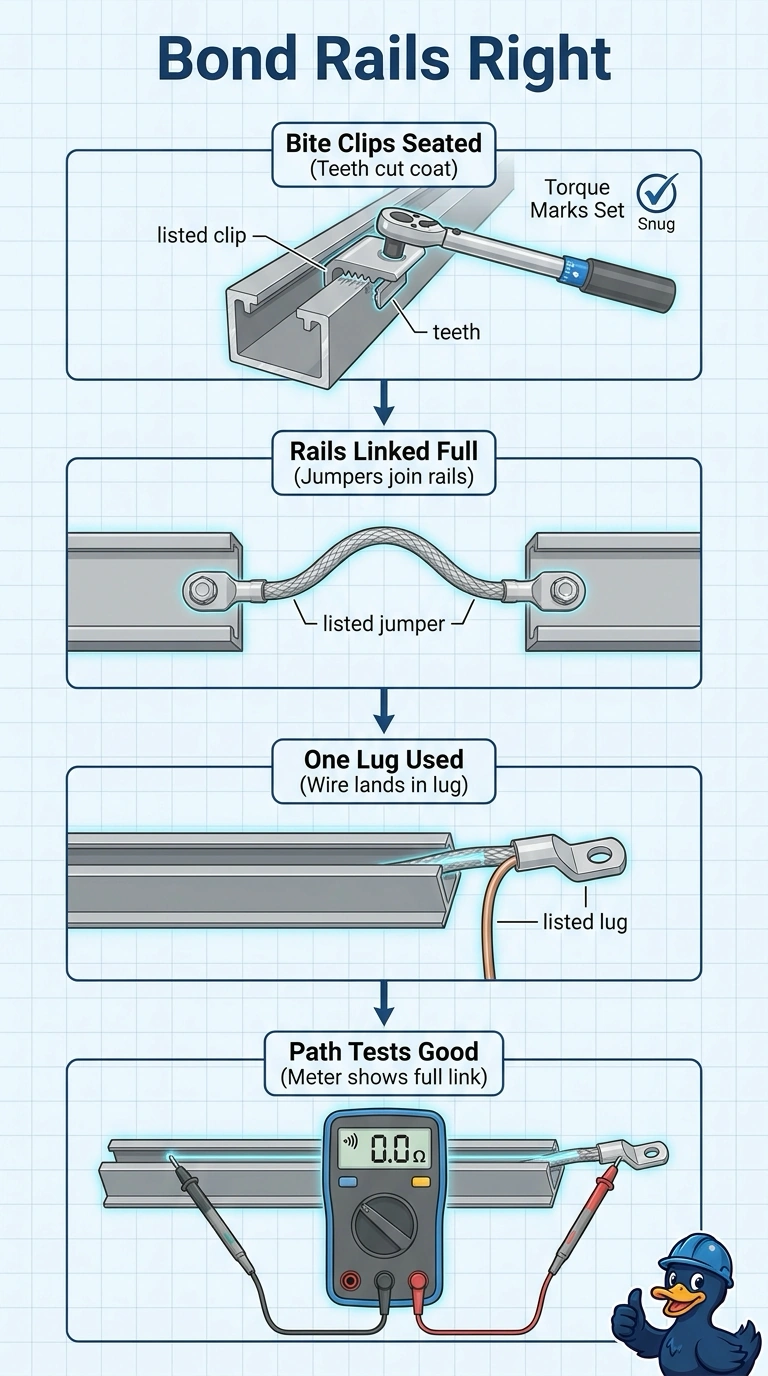
You’ll maintain a continuous fault path by seating the listed clips at the specified torque, linking the rails with listed jumpers, and landing one equipment-grounding wire in the listed lug. Each approved connection helps keep the path complete, with no field improvising needed.
Full Explanation
The listed arrangement provides a continuous fault path as a complete system: integrated clips bond the modules to the rails when placed and torqued as specified, listed jumpers maintain continuity between rail sections, and the copper equipment-grounding conductor terminates in the provided copper-rated lug. Listed frame-bonding washers may be familiar, but their listing alone does not establish approval for this particular module-and-rail combination. Listed mechanical splice connectors can join rail sections, but that does not necessarily make them grounding or bonding components, so continuity across the joint is not assured. Mounting the copper-rated lug with ordinary hardware not specified for it departs from the evaluated installation and may compromise its mechanical or electrical connection. Exam caveat: a component described as listed is not automatically suitable for every bonding application; check its listing and instructions for the specific equipment and use. Practical check: verify clip and jumper placement, torque values, lug conductor range and copper suitability, and the lug’s specified mounting hardware against the rail-system instructions before inspection.