
A crew lead asks how a multimeter can check continuity of the equipment bonding path from a module frame to the designated equipment grounding point. Which demonstration best checks that path’s continuity?
Select an answer to reveal the explanation.
Short Explanation
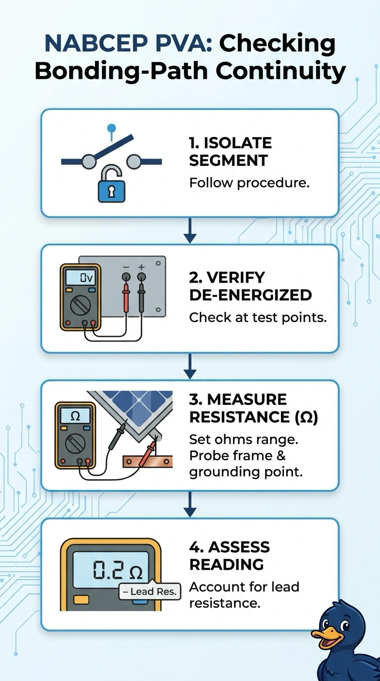
You’ll want to isolate the test segment, verify it’s de-energized, and measure resistance end to end. A low reading is like an open road between two points, but it checks continuity—it doesn’t prove the path can safely carry fault current.
Full Explanation
The correct method checks the bonding path from the module frame to the designated equipment grounding point with the test segment isolated and confirmed de-energized. Measuring resistance end to end directly assesses continuity without parallel paths masking an open connection or energized conductors creating a hazard. Measuring from the frame to the ground bar without isolating parallel bonding paths could show continuity through another bonded component even if the specific path being assessed is open. Measuring only to the nearest mounting rail does not verify the complete path to the designated grounding point; the rail may be bonded to the grounding system, but that is not the specified endpoint. Using continuity mode to the designated ground point and accepting an audible beep as proof is insufficient because meter beeper thresholds vary and may not reveal resistance high enough to compromise a bonding connection. A resistance reading is more informative for this check. Exam caveat: continuity mode also measures resistance, but a beep alone does not demonstrate that the measured value is acceptably low. Practical check: inspect the meter leads and connections, and account for lead resistance when evaluating a low-resistance result.