
At a 30-kW shop the portal shows solar output far below the inverter screen, and the tech finds small doughnut sensors around the feeders plus small boxes tied to voltage leads in the monitor panel. Which monitoring equipment explanation correctly describes current and potential transformers?
Select an answer to reveal the explanation.
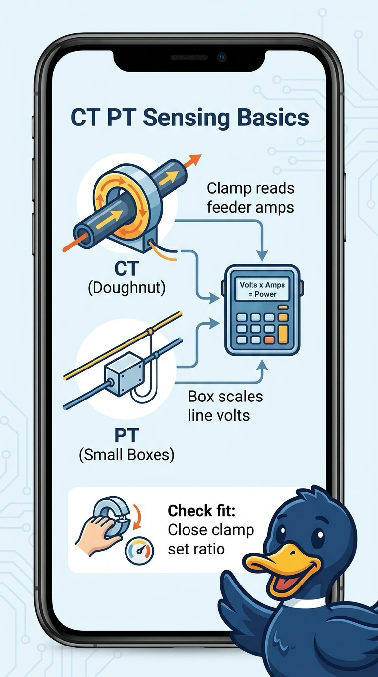
Short Explanation
You’re sorting sensors from their function, and that can point you toward the fix fast. Getting sensing right is like knowing a speed gun only watches cars.
Full Explanation
Current transformers (CTs) sense current in a conductor and provide a scaled signal to monitoring equipment, while potential transformers (PTs) scale voltage from the voltage leads so the monitor can combine voltage and current to calculate power. This matches the doughnut-shaped sensors around the feeders and the small boxes connected to voltage leads. Measuring inverter-output current with CTs and scaling voltage with voltage transformers is a valid arrangement, but it places the current measurement on the inverter output rather than the feeder shown; that location can produce a different reading from the feeder measurement described. Residual-current transformers detect imbalance or leakage current, but that is not the feeder-load current measurement needed for the portal’s production calculation. Using CTs to sense feeder current is correct, but describing PTs as providing voltage only for protection relays omits their role in scaling voltage for portal power math. Exam caveat: CTs and PTs may have different names or forms in different systems, and one instrument can serve more than one function, so identify the actual wiring and destination of its signal. Practical check: compare the monitor’s CT orientation, phase assignment, and ratios with its configuration, then verify that the voltage leads and CT signals correspond to the same phases and measurement point.