
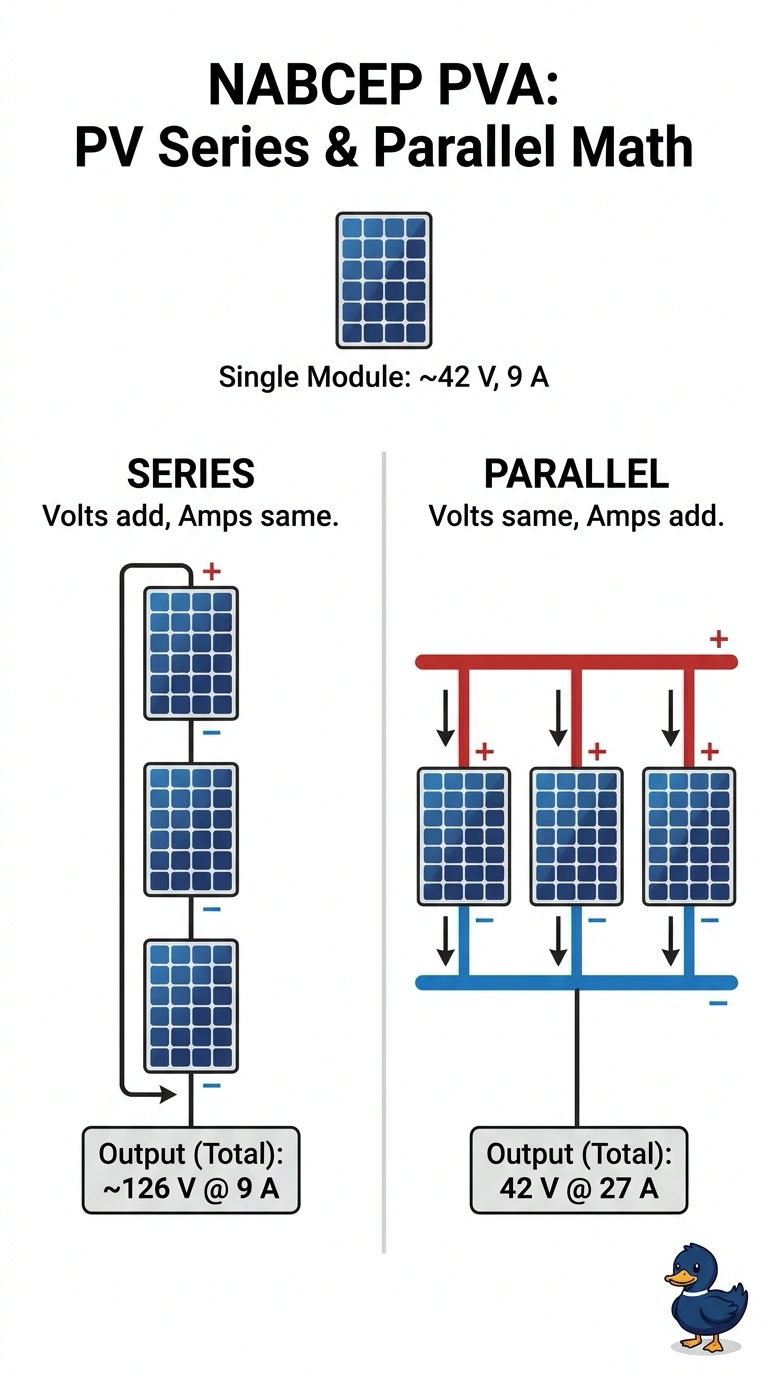
On a shed demo board a trainer has three identical 42-V open-circuit, 9-A short-circuit modules feeding one fused homerun. Trainees must predict meter readings before covering and uncovering modules. Which series versus parallel circuit calculation correctly predicts total voltage and current for the demo?
Select an answer to reveal the explanation.
Short Explanation
You're stacking versus sharing, and the math follows the wiring path. Nailing addition here is like knowing stairs add height while lanes add cars.
Full Explanation
Series wiring forces the same current through every module so voltages add while current stays at one module value, giving about 126 V at 9 A, whereas parallel wiring holds a common voltage so currents add while voltage stays at one module value, giving 42 V at 27 A, which predicts fuse loading and meter readings. Adding current in series fails by concept because it confuses parallel addition with the single-path rule for series current. Adding both voltage and current in parallel fails by concept because it mixes both rules and violates the common-voltage constraint of parallel branches. Claiming totals never change fails by concept because it ignores that topology determines which quantity sums. Exam caveat: use open-circuit voltage and short-circuit current for the predicted totals only when the trainer specifies those test conditions. Practical check: draw three blocks in a line for series with one current arrow, then side by side for parallel with three current arrows joining.