
On a rail-mounted home array, the plan calls the aluminum rails the equipment grounding path using WEEB-style clips between modules and rails plus a single lug to the grounding conductor. Which check should the installer perform to apply integrated grounding and listed bonding components?
Select an answer to reveal the explanation.
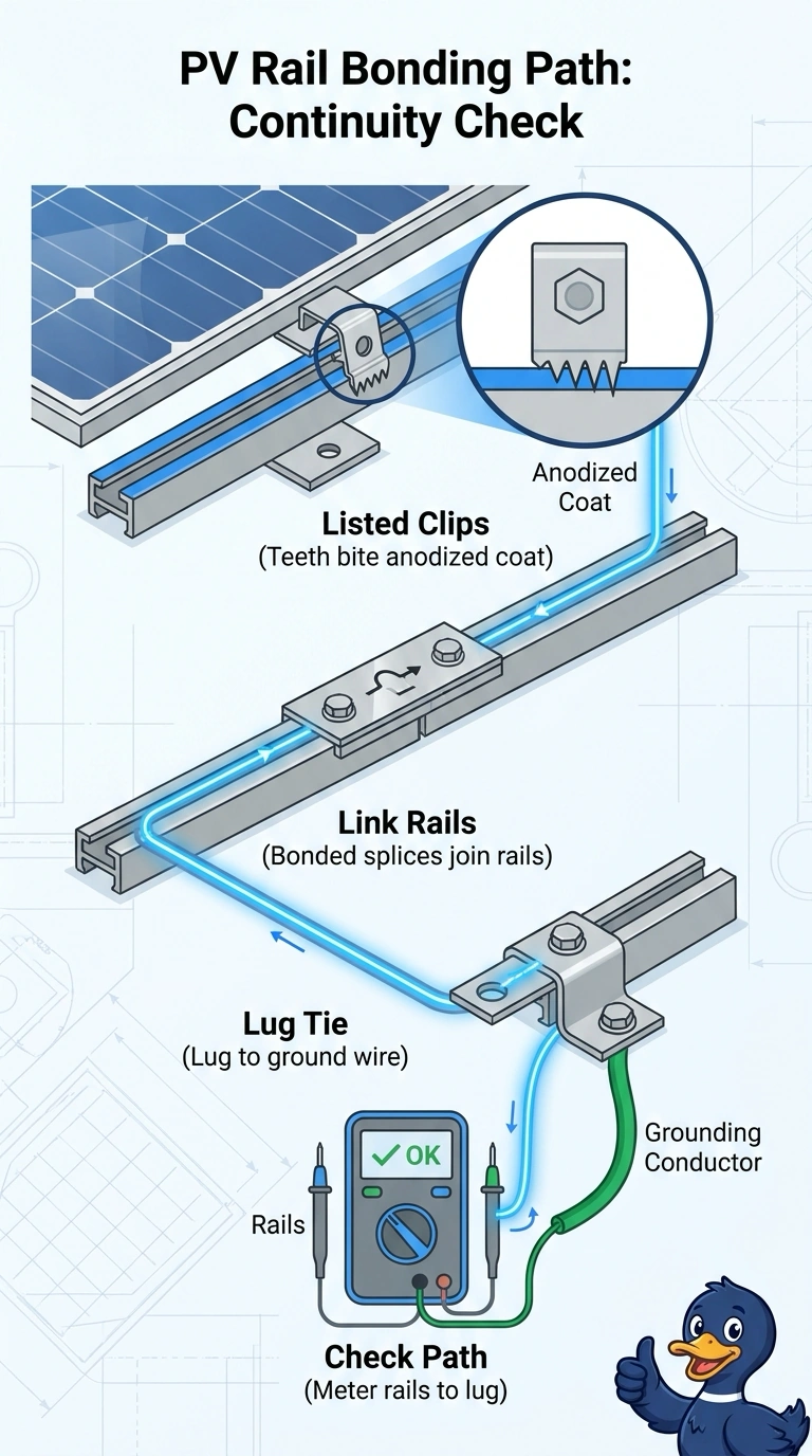
Short Explanation
Check that the listed clips pierce the rails’ anodized coating and bond the modules and rails together, then make sure the lug connects the rail assembly to the grounding conductor. The coating is like an invisible raincoat, so the clips must bite through it to maintain continuity.
Full Explanation
The required check covers the complete integrated bonding path: listed clips must pierce the anodizing to make the specified connection, the rail sections must be electrically linked, and the lug must connect the rail assembly to the grounding conductor. Checking the clips and rail bonding but relying on the mount instead of a grounding lug leaves the required connection to the grounding conductor unverified; mechanical attachment alone does not prove that connection. Checking the clips and lug but assuming splice bars bond the rails leaves rail-to-rail continuity unverified, unless the splice arrangement is listed or otherwise established as providing that bond. Checking rail continuity and the lug while using listed washers on scraped metal instead of clips that pierce anodizing relies on a different contact method; the hardware and surface preparation must match the equipment instructions. Exam caveat: bonding methods are product- and listing-specific, so do not assume every splice, washer, or rail assembly provides an acceptable path. Practical check: consult the module and racking instructions, inspect the installed clips, rail joints, and lug, and verify continuity by the manufacturer- or code-prescribed method.