
A junior installer is fitting rails on a 96-module ground-mount array. At every post-to-rail joint the layout sheet shows a circle split by a horizontal line, with 4 above it and S2 below. The set also holds a site plan, an equipment schedule and an electrical single-line, and she needs to see how the rail seats in the post cap and how the splice is made. Which sheet does that callout point her to?
Select an answer to reveal the explanation.
Short Explanation
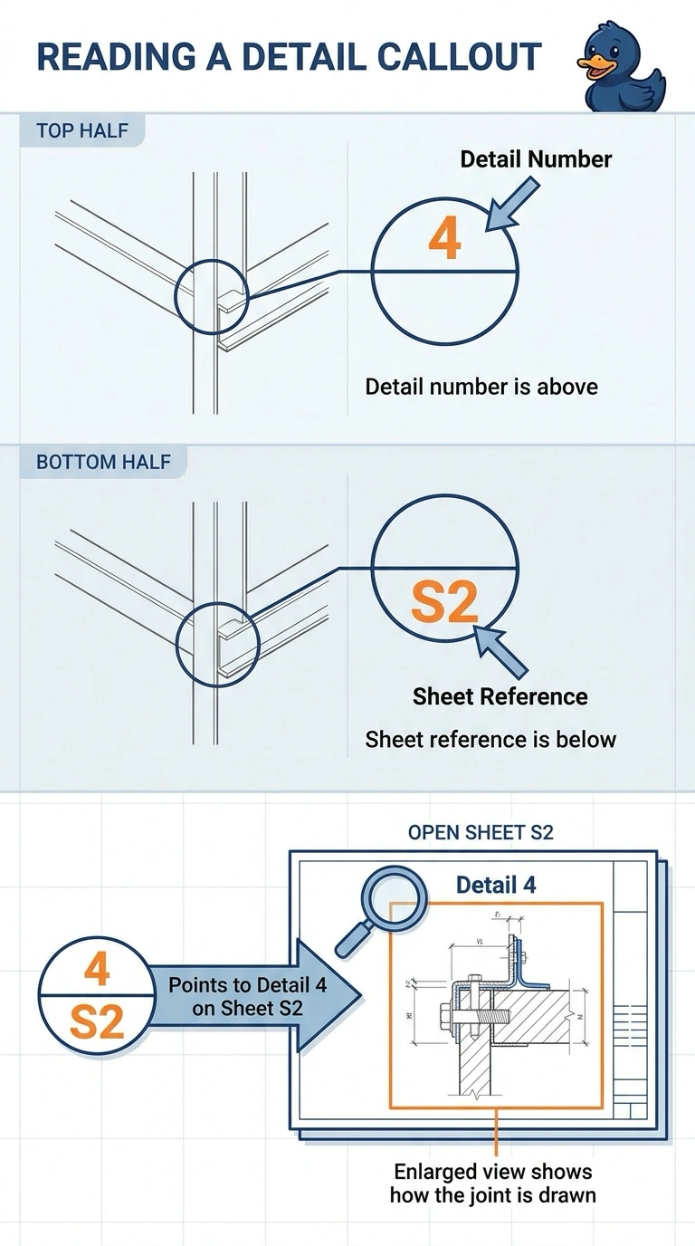
You can read the split callout as an address: 4 above S2 sends you to detail 4 on sheet S2. That enlarged view shows how the rail seats in the post cap and how the splice is made, so check it before installation.
Full Explanation
A split-circle detail callout conventionally places the detail number above the dividing line and the sheet identifier below it. Here, 4 identifies the detail and S2 identifies the sheet, so the callout directs you to detail 4 on sheet S2; that enlarged view shows how the rail seats in the post cap and how the splice is made. The suggestion to use detail 4 on sheet S1 preserves the detail number and describes the needed connection, but changes the sheet identifier and sends you to the wrong sheet. The suggestion to use detail 5 on sheet S2 keeps the correct sheet and connection description, but changes the detail number; a nearby or similarly named detail is not a substitute for the number actually called out. The suggestion to use detail 4 on sheet S2 for the splice but consult the schedule for the post-cap seat keeps the correct callout for part of the work, but a schedule normally identifies or specifies components rather than showing their assembled geometry, so it does not meet the need to see the seat. Exam caveat: drawing sets may use different callout graphics, so verify the legend or drafting conventions if the notation is unclear. Practical check: open sheet S2, locate detail 4, and confirm that its drawing shows both the rail-to-cap fit and the splice before using it for installation.