
You are sizing a home with 9.6 kW DC of modules paired to a 7.6 kW AC inverter for a south roof with no shade and a tight budget. The inverter max DC input and voltage window both pass. Which compatibility check confirms the DC:AC ratio supports expected clipping and output?
Select an answer to reveal the explanation.
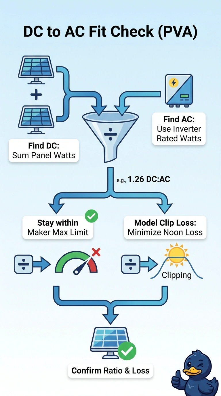
Short Explanation
You've got this — clipping is normal when panels out-muscle the inverter a bit. Your DC:AC ratio is like a funnel that spills a little at peak sun to save cash.
Full Explanation
The 1.26 DC:AC ratio is the module array’s 9.6 kW DC rating divided by the inverter’s 7.6 kW AC rating. Confirming it is within the inverter maker’s permitted design limits addresses equipment compatibility; modeling clipping under the south roof’s actual, unshaded conditions estimates how often DC power will exceed the inverter’s AC capacity and how much energy will be lost. This gives a more meaningful expectation of delivered output than the ratio alone. Comparing the ratio with common design ranges and modeling clipping for this roof is a reasonable preliminary design method, but it does not establish that the particular inverter maker permits that array-to-inverter ratio. Checking maker limits while using a standard regional clipping profile can confirm equipment constraints, but a generic profile may not represent this roof’s orientation, local irradiance, temperature, or other site conditions, so it does not meet the site-specific modeling requirement. Checking maker limits and modeling site clipping still falls short if the energy calculation uses unclipped DC production as delivered energy: it fails to subtract energy the inverter cannot convert during clipping. Exam caveat: the ratio is a useful screening metric, not a universal pass/fail threshold; applicable inverter input limits and design rules still govern. Practical check: use the project’s module and inverter data with a site-specific production model, and review both modeled clipping losses and net AC energy.