
A cooperative's network engineer segments subscribers in a small town into two VLANs on the same aggregation switch, specifically so that an ARP broadcast sent by a customer in VLAN 10 does not reach devices in VLAN 20. What has effectively been created between the two VLANs?
Select an answer to reveal the explanation.
Short Explanation
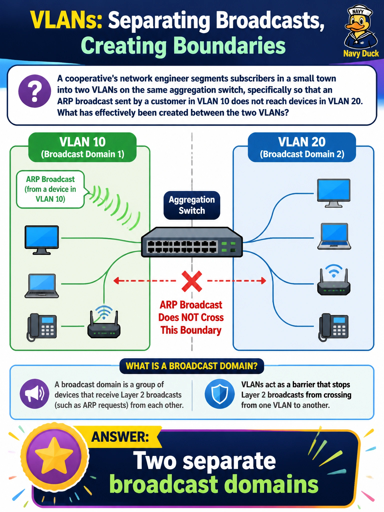
Splitting subscribers into two VLANs is like putting up a wall between two rooms so a shout in one room doesn't wake up the other. Each VLAN becomes its own broadcast domain, so an ARP broadcast in VLAN 10 simply never reaches anyone sitting in VLAN 20.
Full Explanation
A broadcast domain is the boundary within which a broadcast frame — such as an ARP request — is delivered to every device. Configuring separate VLANs on a switch creates exactly that kind of boundary at Layer 2: each VLAN is treated as its own logically isolated broadcast domain, so a broadcast originating in VLAN 10 is flooded only to other ports in VLAN 10, never to VLAN 20, even though both VLANs live on the same physical switch. Describing the result as one larger collision domain confuses two different scopes; collision domains concern simultaneous transmissions colliding on shared media, which VLANs don't address at all, and modern switched, full-duplex ports already keep collision domains small regardless of VLAN configuration. Saying the two VLANs share a single broadcast domain is the opposite of what VLAN segmentation accomplishes — it would mean the ARP broadcast reaches both groups, defeating the engineer's purpose. Calling it a single, VLAN-isolated collision domain mixes the two concepts and doesn't describe any real state the switch is in. For a technician verifying this configuration, a useful operational check is to generate a broadcast (such as an ARP request) from a test host in VLAN 10 and confirm, via a packet capture on a VLAN 20 port, that the frame never arrives — proof the broadcast domains are genuinely separated.