
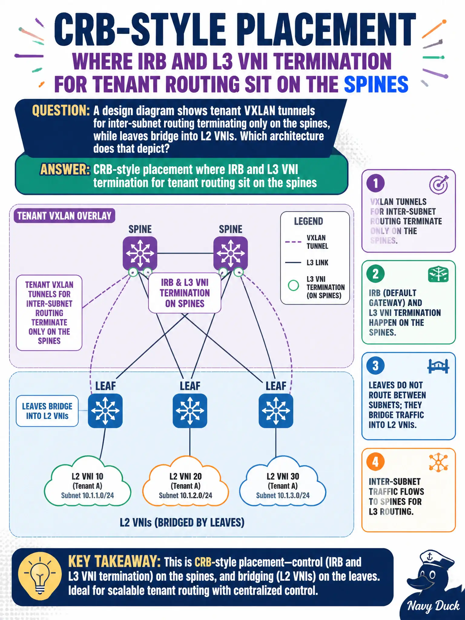
A design diagram shows tenant VXLAN tunnels for inter-subnet routing terminating only on the spines, while leaves bridge into L2 VNIs. Which architecture does that depict?
Select an answer to reveal the explanation.
Short Explanation
If only the spines finish the VXLAN/IRB for tenant routing, you are looking at CRB. Leaves bridge; spines route between subnets. ERB would show IRB on the leaves, and plain underlay or DCI stitching is a different picture.
Full Explanation
A diagram that shows tenant VXLAN tunnels for inter-subnet routing terminating only on the spines, while leaves bridge into L2 VNIs, depicts CRB-style placement: IRB and L3 VNI termination for tenant routing sit centrally. That is not ERB with anycast gateways and L3 VNIs on every leaf. It is not underlay-only ECMP with no overlay VNI encapsulation. It is not DCI stitching across sites without a local EVPN instance—though DCI borders can separately terminate overlays. Exam caveat: some drawings label spine gateway loosely; verify whether leaves still have IRBs (hybrid) before calling it pure CRB on the exam. Operational check: inventory IRB and L3 VNI presence device-by-device in the city fabric, match the diagram to CRB if only spines or borders terminate tenant L3, and traceroute inter-subnet traffic to confirm central termination. Require diagrams to list IRB locations explicitly; a picture with VXLAN arrows alone is not enough for CRB/ERB classification. Require diagrams to list IRB locations explicitly; a picture with VXLAN arrows alone is not enough for CRB/ERB classification. Require diagrams to list IRB locations explicitly; a picture with VXLAN arrows alone is not enough for CRB/ERB classification.