
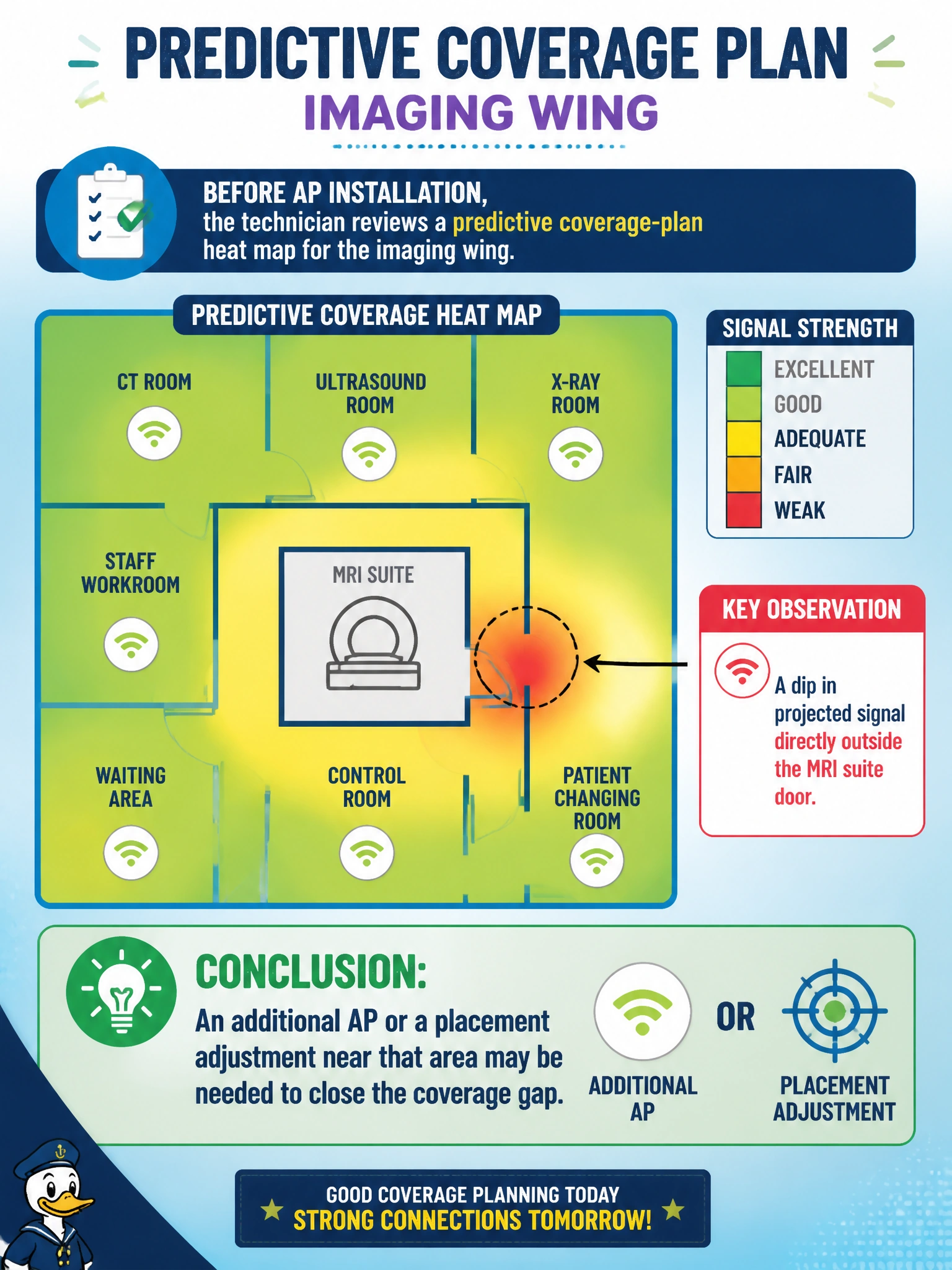
Before AP installation, the technician reviews a predictive coverage-plan heat map for the imaging wing. The map shows adequate projected signal everywhere except a dip directly outside the MRI suite door. What should the technician conclude from this output?
Select an answer to reveal the explanation.
Short Explanation
A coverage-plan heat map is basically a weather forecast for Wi-Fi signal — it's telling you where a storm of dead zones is likely before you ever plug in a single AP. A dip outside a shielded room like an MRI suite is exactly the kind of spot heavy walls and RF shielding chew up signal. Reading that dip correctly means treating it as a cue to add or move an AP, not a reason to shrug it off.
Full Explanation
A predictive heat map models expected signal strength across a floor plan using building materials, AP locations, and RF propagation estimates, so a localized dip is a design signal pointing at a specific spot, not random noise. MRI suites are typically heavily shielded to contain the machine's magnetic field, and that same shielding attenuates Wi-Fi signal in the surrounding corridor, which is a very plausible cause of the dip shown here. Relocating the MRI machine confuses cause and effect — the imaging equipment's placement is fixed by clinical requirements, and RF design has to work around it, not the other way around. Dismissing the map because it's "only predictive" misunderstands its purpose: predictive surveys exist precisely to catch gaps like this before cabling and mounting hardware are installed, saving a costly rework later. DHCP scope sizing is unrelated to signal strength; running out of IP addresses produces connection failures, not an RSSI dip on a coverage map. The correct response to this kind of finding is to treat it as an input into AP placement — adding an AP nearby, adjusting an existing AP's location, or reorienting an antenna — and then re-running the prediction or validating with an on-site measurement once hardware is installed to confirm the gap actually closed.