
The accessory kit holds two lengths of storage interconnect cable, and the planned layout puts the expansion shelf several rack units below the head unit. What does the checklist's cabling section call for before the install day?
Select an answer to reveal the explanation.
Short Explanation
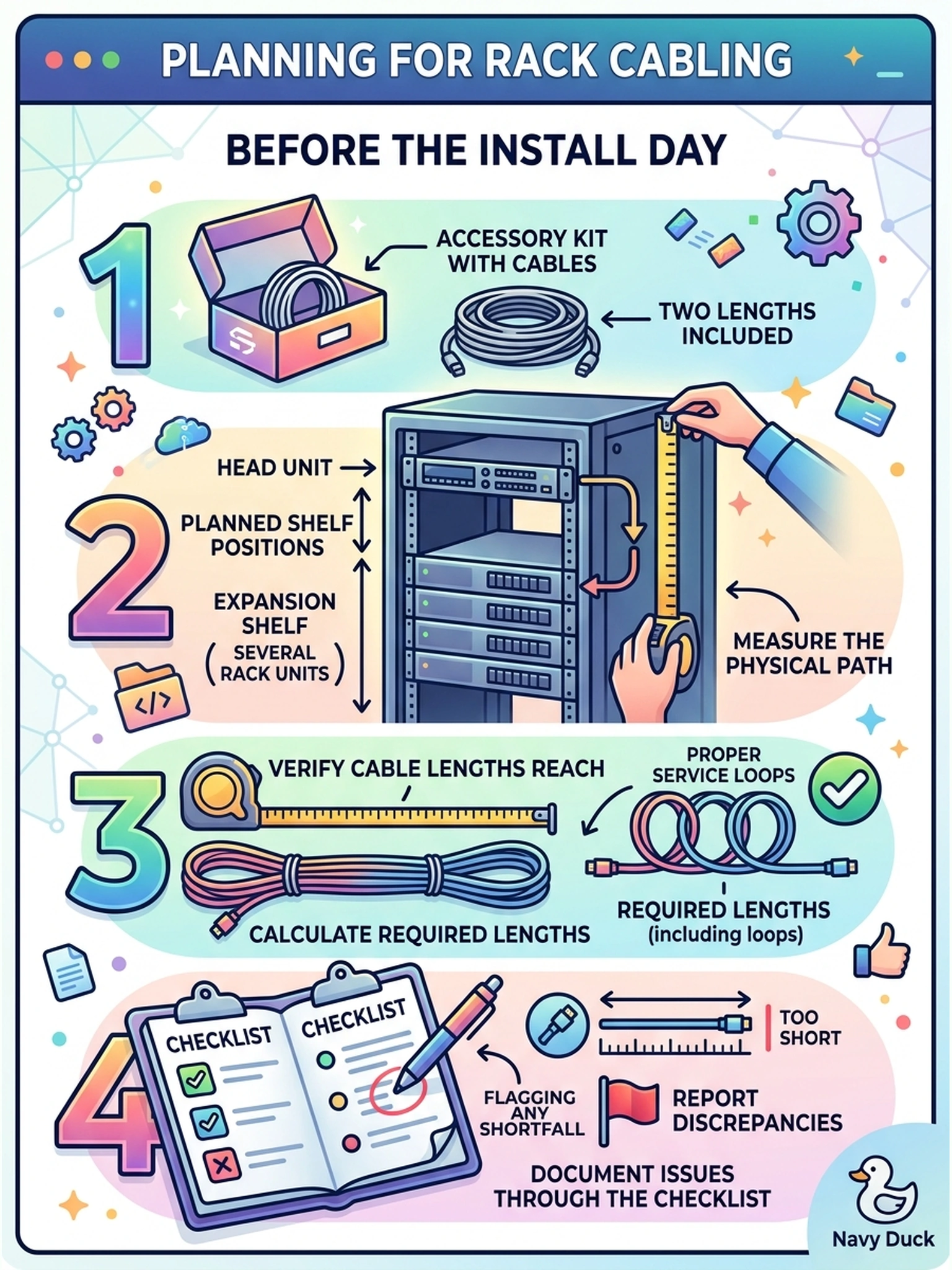
Nothing kills install-day momentum like a cable two inches short. The checklist has you measure the real path for every interconnect before the rack work starts, because the fix is cheap on paper and expensive at two in the afternoon. Tape measure first, screwdriver second—that's the order.
Full Explanation
Storage interconnects come in fixed lengths, and the physical path—down a runner, around a bend, up to the port—is always longer than the straight-line gap between two boxes. The cabling section compares the kit's lengths against the planned layout before the rack work commits, including the service loop that lets a shelf be serviced without unplugging under tension. Daisy-chaining additional segments fails by concept: expansion topologies are documented chains with defined ordering; arbitrary links added because connectors mate are unsupported. Auto-negotiation fails the same way—negotiation settles link speed and width, not meters of physical reach; the length limitation is a property of the cable, not a setting. Choosing shelf position to fit the shortest cable inverts the planning order: layout is driven by weight, documented stacking order and service access; cable convenience is never a layout driver. Routing a marginal cable taut, without a loop, is the same shortfall hiding. Exam caveat: part numbers and maximum run lengths come from the shelf's installation guide; the checklist forces the comparison. Operational check: trace each interconnect along the actual cable-management route, measure with a tape, compare against both included lengths, and note any needed cable part numbers on the checklist before mounting begins.