
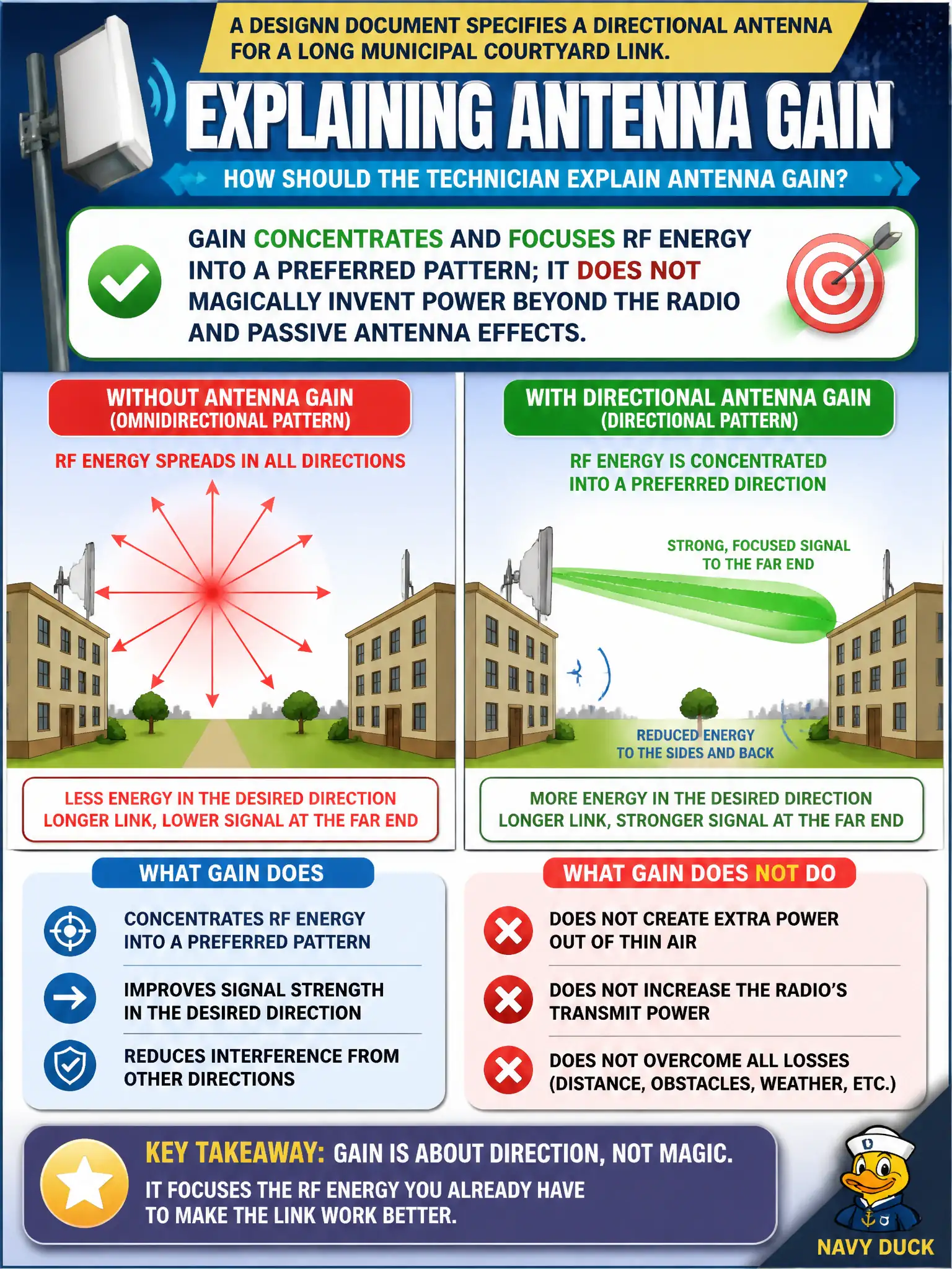
A design document specifies a directional antenna for a long municipal courtyard link. How should the technician explain antenna gain?
Select an answer to reveal the explanation.
Short Explanation
A directional antenna is like a megaphone — same voice, more energy pointed where you aim, less spilled sideways. You did not invent a louder throat; you focused what the radio already puts out. That is gain at technician depth.
Full Explanation
Antenna gain at CWTS depth concentrates and focuses RF energy into a preferred radiation pattern; a directional antenna for a long municipal courtyard link improves effective signal along the aim at the expense of other directions. Passive gain does not magically invent watts beyond the radio’s output as shaped by the antenna system, so claiming gain creates unlimited power without tradeoffs is wrong. Gain is not a control that raises carrier frequency into 6 GHz, and it is not identical to free-space path loss, which grows with distance rather than being “gain.” Exam caveat: regulatory EIRP limits still apply—directional gain can raise effective radiated levels in the beam, so installers must follow the city’s approved power and antenna sheet. Operational check: mount and aim per the courtyard design, verify connector torque and weather sealing, measure link levels along the intended path and confirm reduced coverage off-axis, and document that gain is pattern focusing—not free power or a band change. In municipal WLAN operations, record the rationale in the work order so future on-call staff know which RF concept applied and which failure modes the rejected options would create for city services. Re-validate after the next maintenance window that the same control still holds under the AP firmware and client mix used by the civic network team.