
A regional hospital is inserting an FTD appliance in transparent mode between its core switch and its imaging servers, which must keep their current addresses. A second interface pair connects a partner clinic link that must stay in its own broadcast domain. Which bridge group design meets both requirements?
Select an answer to reveal the explanation.
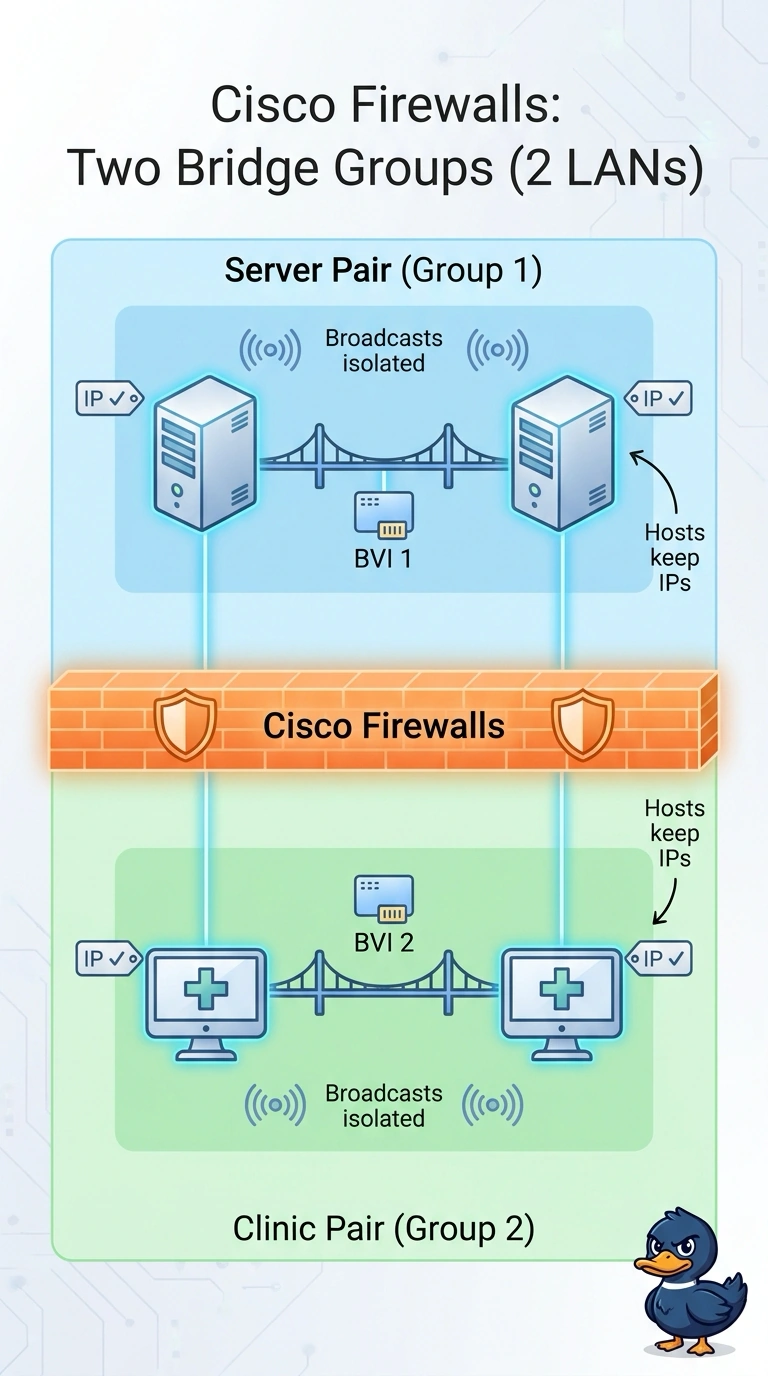
Short Explanation
Put the server interfaces in one bridge group and the clinic interfaces in another, with a BVI for each, so your servers can keep their current addresses while the clinic stays in its own broadcast domain. Each bridge group works like a small switch, so the grouping—not a filter rule—sets the Layer 2 boundary.
Full Explanation
In transparent mode the appliance bridges at Layer 2. Interfaces assigned to a bridge group share that group's broadcast domain, and each group has one BVI. Placing the server-facing pair in one bridge group and the clinic pair in a second meets the stated requirements: the servers keep their addresses, and the two groups have separate broadcast domains. This does not by itself prevent routed traffic between the groups if routing and policy allow it. Putting all four interfaces in one bridge group and assigning the clinic link its own security zone does not separate their broadcast domains; a zone is a policy construct, not a Layer 2 boundary. Configuring the pairs as routed ports would not meet the requested transparent-mode design. Adding a second BVI to one bridge group is unsupported and would not split its broadcast domain. Transparent mode also applies Layer 2 controls, so the appliance is not simply a dumb wire.