
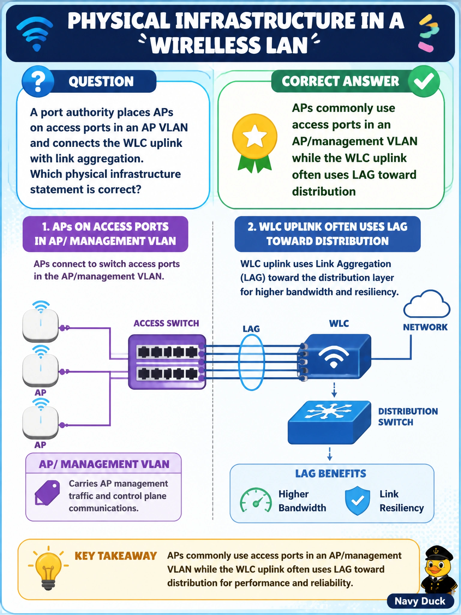
A port authority places APs on access ports in an AP VLAN and connects the WLC uplink with link aggregation. Which physical infrastructure statement is correct?
Select an answer to reveal the explanation.
Short Explanation
Picture APs as cars using an access-port driveway in their own VLAN, while the WLC is a busy ferry dock that can use LAG—multiple cables acting as one resilient link toward distribution. You can remember this standard WLAN cabling pattern without putting every AP on a campus-wide trunk.
Full Explanation
Typical Cisco WLAN physical design places access points on access-mode switch ports in an AP or management VLAN, while the wireless LAN controller uplink toward distribution often uses link aggregation for bandwidth and resiliency. This gives you a clean AP edge—one VLAN on an access port—and a stronger WLC attachment through LAG, without requiring every AP to use a native-VLAN trunk carrying all campus VLANs. Requiring that trunk for every AP over-complicates the edge and is not the common access-port pattern for CAPWAP APs. Requiring the WLC to use only a single non-redundant copper patch rejects the capacity and resiliency benefits of aggregation. Claiming LAG is reserved for printers and must never face a WLC is arbitrary; controllers are good candidates for aggregated uplinks. Exam caveat: some designs trunk AP ports when multiple locally switched VLANs are needed at the edge, such as in certain FlexConnect cases, but the default teaching model for CAPWAP APs is an access port in an AP VLAN. Keep AP port mode distinct from WLC uplink design. Practical check: verify AP switch ports are access ports in the AP VLAN with PoE, confirm APs receive DHCP/IP addresses and join the WLC, and confirm the WLC LAG members are bundled and forwarding toward distribution.