
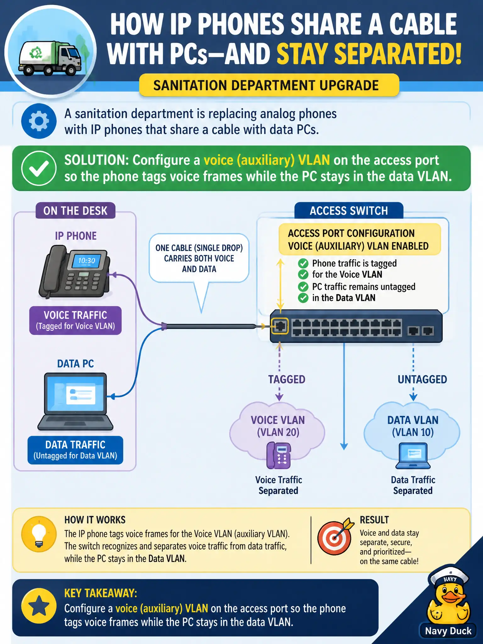
A sanitation department is replacing analog phones with IP phones that share a cable with data PCs. How should the access switch typically separate voice and data traffic on that single drop?
Select an answer to reveal the explanation.
Short Explanation
One cable, two jobs—like a dual-lane driveway. The voice VLAN is the phone’s tagged lane; the PC stays in the untagged data lane. That auxiliary VLAN pattern keeps desk phones and PCs sharing copper without sharing one broadcast domain.
Full Explanation
Cisco access ports commonly use a data access VLAN plus a voice (auxiliary) VLAN: the IP phone tags voice frames with the auxiliary VLAN while the attached PC uses the untagged or access VLAN on the same cable. CDP or LLDP often informs the phone of the voice VLAN. For a sanitation department replacing analog phones, that pattern separates voice and data traffic on a single drop without dual homing every desk.
Forcing the phone and PC into the same native VLAN and marking voice with DSCP only inside the PC OS conflates broadcast domains and trusts endpoint marking without the usual switch-side voice VLAN separation. Running a second physical cable for every phone and disabling CDP/LLDP is optional cabling cost, not the typical design, and disabling discovery can break phone VLAN learning. Configuring the port as a routed Layer-3 interface with two secondary addresses is not the usual desktop phone access pattern—phones expect switched access with voice VLAN, not a per-desk L3 port.
Exam caveat: voice VLAN still needs QoS trust/marking policy and DHCP options; the auxiliary VLAN alone does not guarantee voice quality. Operational check: confirm switchport voice vlan is set, the phone shows the correct voice VLAN via CDP/LLDP, the PC remains in the data VLAN, and a packet capture on the port shows tagged voice versus untagged data as designed.