
A head and neck patient is treated on a 6 MV linac, and today's setup places the skin at an extended 115 cm SSD because the shoulder immobilizer raises the treatment level. The target depth, the field size at the skin, and the beam energy all match the plan calculated at the nominal 100 cm SSD, no wedge or tray is in the beam, and the target sits on the beam axis. Which correction must be applied to the prescribed monitor units for this extended-distance setup?
Select an answer to reveal the explanation.
Short Explanation
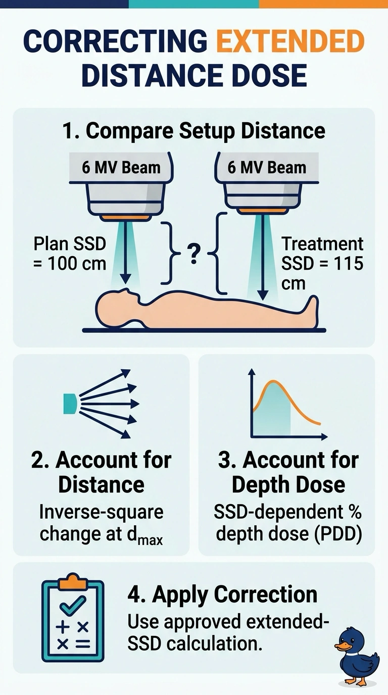
With your setup at 115 cm, distance alone is not enough: output at the depth of maximum dose changes by the inverse-square law, and percentage depth dose also changes with SSD. Use the extended-SSD correction to account for both effects.
Full Explanation
At 115 cm SSD, the MU correction must account for two distinct effects: the dose-reference point at the depth of maximum dose is farther from the source, reducing output by the inverse-square law, and percentage depth dose (PDD) changes with SSD because beam divergence differs. The required extended-SSD correction includes both effects, using the actual geometry and PDD data or a Mayneord F-factor. An inverse-square correction using the source-to-target distance alone assumes nominal-SSD PDD remains valid; unchanged depth and energy do not remove PDD’s SSD dependence. A PDD ratio alone misses the reduced output at the more distant reference point. Applying an SSD-dependent PDD correction and an additional inverse-square factor to the target depth counts the depth falloff twice, since the PDD for the extended SSD already accounts for dose change from the depth of maximum dose to the target. Exam caveat: distinguish SSD-based PDD methods from SAD-based TMR/TPR methods, and do not combine corrections from both formalisms indiscriminately. As a practical check, verify the actual source-to-surface distance and depth of maximum dose, then confirm that the field-size convention and beam data support the selected extended-SSD correction.