
A pelvis case is planned on a 6 MV linear accelerator with the target sitting on the rotation axis at the machine's stated distance, and the gantry travels an arc around that fixed point. The monitor units were written for the axis depth rather than for the skin entry point. Which depth-dose quantity should verify these monitor units for this isocentric setup?
Select an answer to reveal the explanation.
Short Explanation
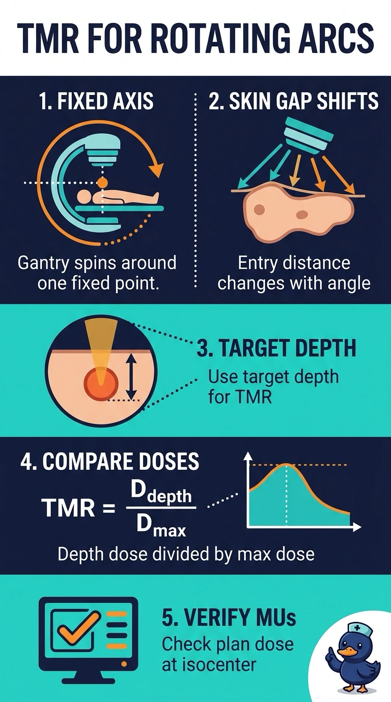
You're checking an arc plan, so the skin entry point keeps moving while the target stays put. The tissue maximum ratio compares dose at depth to dose at maximum buildup without assuming any fixed skin distance, which is exactly what this geometry needs. Output factor tables and fixed-skin depth tables each cover only one piece of that job.
Full Explanation
In an isocentric setup the rotation axis stays fixed while the surface distance changes with every degree of gantry travel, so the beam entry point is never at a constant reference. The tissue maximum ratio compares dose at a stated depth to dose at the depth of maximum buildup for a beam aimed through the axis, and because it is referenced inside the phantom it does not depend on where the skin lies, which makes it the right quantity for arc and rotational delivery. Percentage depth dose tables are constructed for a fixed source-to-surface distance, so using them while that distance shifts builds a systematic error into the plan check. Tissue-air ratio is not the standard depth-dose quantity used for megavoltage linac isocentric calculations; tissue maximum ratio is. Head output factors describe how output changes with jaw setting at calibration and say nothing about attenuation in tissue. Exam caveat: the distinction tested is usually fixed SSD versus isocentric geometry rather than a numerical table lookup. Practical check: confirm whether the monitor units were written at the skin or at the axis before choosing any depth quantity.