
During the final check of an isocentric 6 MV plan, the isocenter sits at the standard 100 cm source-to-axis distance and 6.0 cm deep in the target, the prescription is 200 cGy at that point, the beam is open with no wedge, and the MLC shapes the aperture. The machine output for this aperture is 1 cGy per monitor unit at the calibration depth of maximum dose. Which calculation best verifies the monitor units for this beam?
Select an answer to reveal the explanation.
Short Explanation
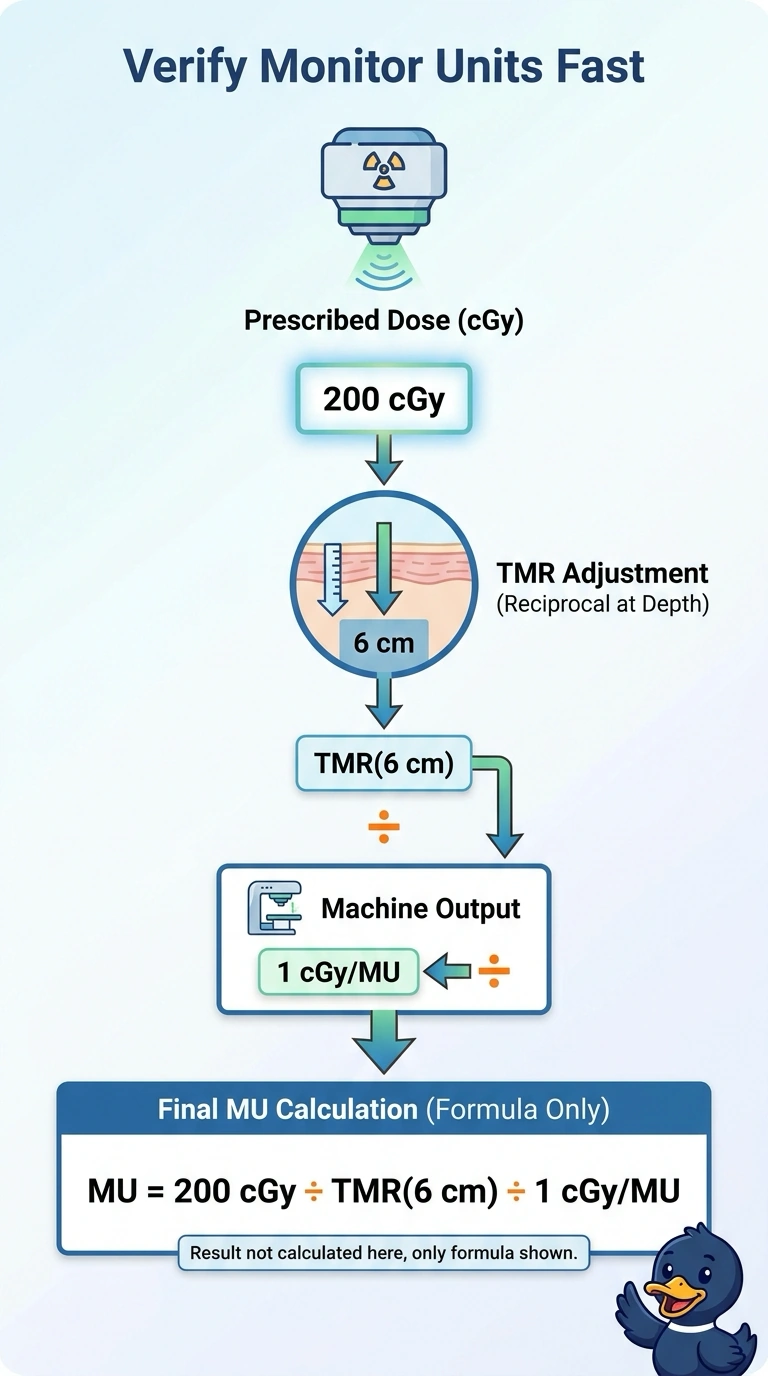
Use the TMR as a conversion bridge between the dose at 6 cm and the dose at the calibration depth: multiply 200 cGy by the reciprocal of the TMR at 6 cm, then divide by the aperture’s output of 1 cGy/MU. Since there’s no wedge and the output already matches your MLC-shaped aperture, no extra corrections are needed.
Full Explanation
Because the plan is isocentric, the source-to-axis distance stays fixed as the calculation moves from the calibration depth of maximum dose to the internal prescription point. The tissue-maximum ratio relates dose at that depth to dose at the reference depth under this geometry, so the monitor units are the prescribed dose divided by the TMR and the stated output. A percent-depth-dose workflow is associated with a fixed-SSD geometry and is not the appropriate ratio here. A wedge factor is inapplicable because the beam has no wedge. The stated output is for this aperture, so an additional MLC transmission correction is not called for in this calculation. Confirm the depth and reference conditions used for the TMR against the calculation data.