
On a Juniper EVPN-VXLAN municipal leaf, how are Layer 2 and Layer 3 tenant isolation mechanisms typically mapped?
Select an answer to reveal the explanation.
Short Explanation
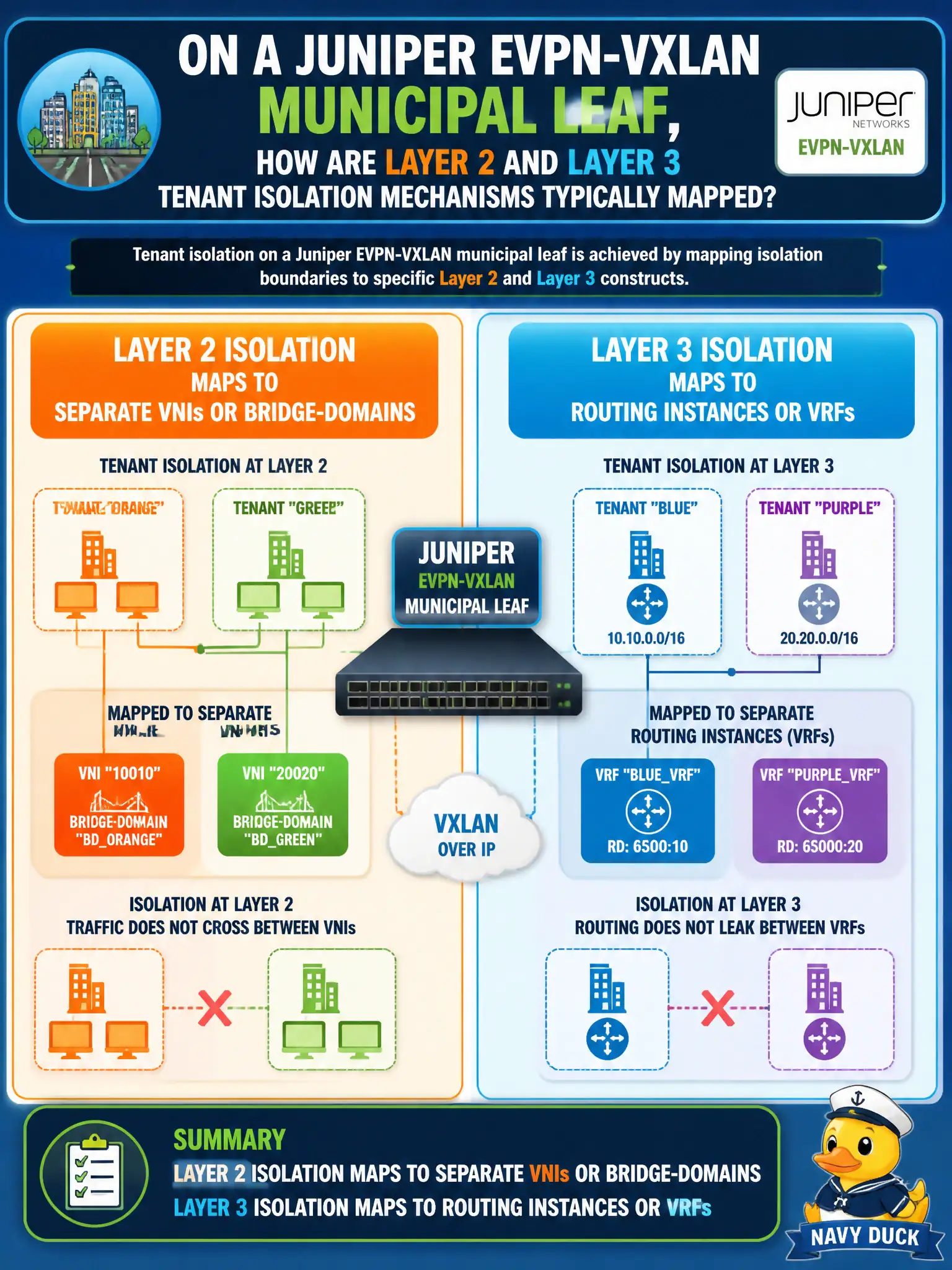
L2 isolation is about separate broadcast rooms (VNIs/bridge-domains). L3 isolation is about separate map books (routing instances/VRFs). Loopbacks and CoS are useful, but they are not the tenant-isolation map you draw for JN0-683.
Full Explanation
On a Juniper EVPN-VXLAN municipal leaf, Layer 2 and Layer 3 tenant isolation typically map as follows: L2 isolation maps to separate VNIs or bridge-domains, and L3 isolation maps to routing instances or VRFs. That pairing is the standard describe-level picture for civic multitenancy on QFX-style leaves and keeps broadcasts and routes in the right cabinets.
L2 isolation is not completed only by firewall filters while L3 uses only CoS schedulers—filters and CoS help policy and QoS but are not the primary tenant domain constructs. Unique underlay loopback addresses alone do not finish both L2 and L3 tenant isolation. Identical VNIs for every tenant with a shared VRF invert the model and destroy isolation.
Exam caveat: map L2→VNI/bridge-domain and L3→routing-instance/VRF quickly; distractors often substitute QoS, filters, or underlay addressing.
Operational check: for two agencies, display separate bridge-domains/VNIs and separate routing instances, then verify broadcasts and routes stay inside each mapping during a controlled ping and ARP test. Archive show bridge-domain and show route instance outputs as audit artifacts whenever a new agency onboards. Retain before-and-after show commands in the change ticket so the municipal NOC can prove the isolation or steering outcome without relying on memory.