
A repeat AP supine abdomen looks flat with grainy noise throughout the liver shadow, and the exposure indicator is far from the department baseline despite standard kVp and correct positioning. The image was processed normally with no grid cutoff. Which exposure indicator interpretation should the technologist apply to correct gross exposure errors?
Select an answer to reveal the explanation.
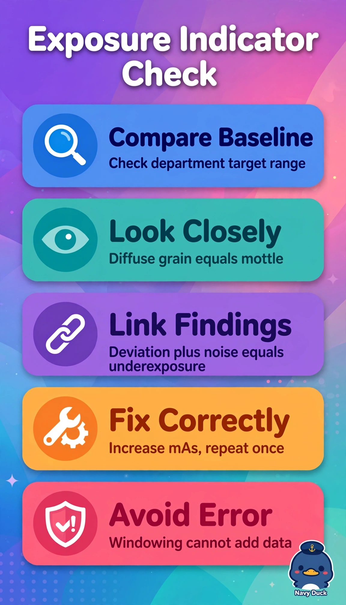
Short Explanation
You're reading the detector's fuel gauge, not just the picture. Linking the stray indicator to visible grain points to too little dose reaching the plate, like static on a weak signal.
Full Explanation
The exposure indicator quantifies detector exposure relative to a department-calibrated target and must be correlated with image appearance, where gross underexposure produces quantum mottle and loss of low-contrast detail that cannot be rescued by windowing because insufficient photons create statistical noise. Adjusting window to smooth noise while accepting the deviation fails by concept because postprocessing alters brightness and contrast presentation but does not restore missing information or correct the out-of-range detector dose. Repeating with substantially reduced mAs for presumed overexposure fails by concept because overexposure in digital systems typically shows low noise with saturated indicator in the opposite direction, and further reduction would worsen mottle and repeat dose burden. Attributing the finding to grid cutoff and repeating upright with identical technique fails by concept because cutoff creates focal underexposure bands or edge loss from angulation, not uniform grain with indicator deviation. Exam caveat is that indicator direction varies by manufacturer, so always compare to your posted baseline rather than memorizing high versus low. Practical check is to verify technique chart, detector dose calibration, and collimation before repeating once with adjusted mAs.