
During annual compliance testing on a 120-kVp radiographic room with a 40-inch SID, the supervisor asks a graduate technologist to demonstrate congruence between the collimator light field and the radiation field plus central ray accuracy for quality control documentation. Which test method should the technologist perform to verify light field and central ray alignment?
Select an answer to reveal the explanation.
Short Explanation
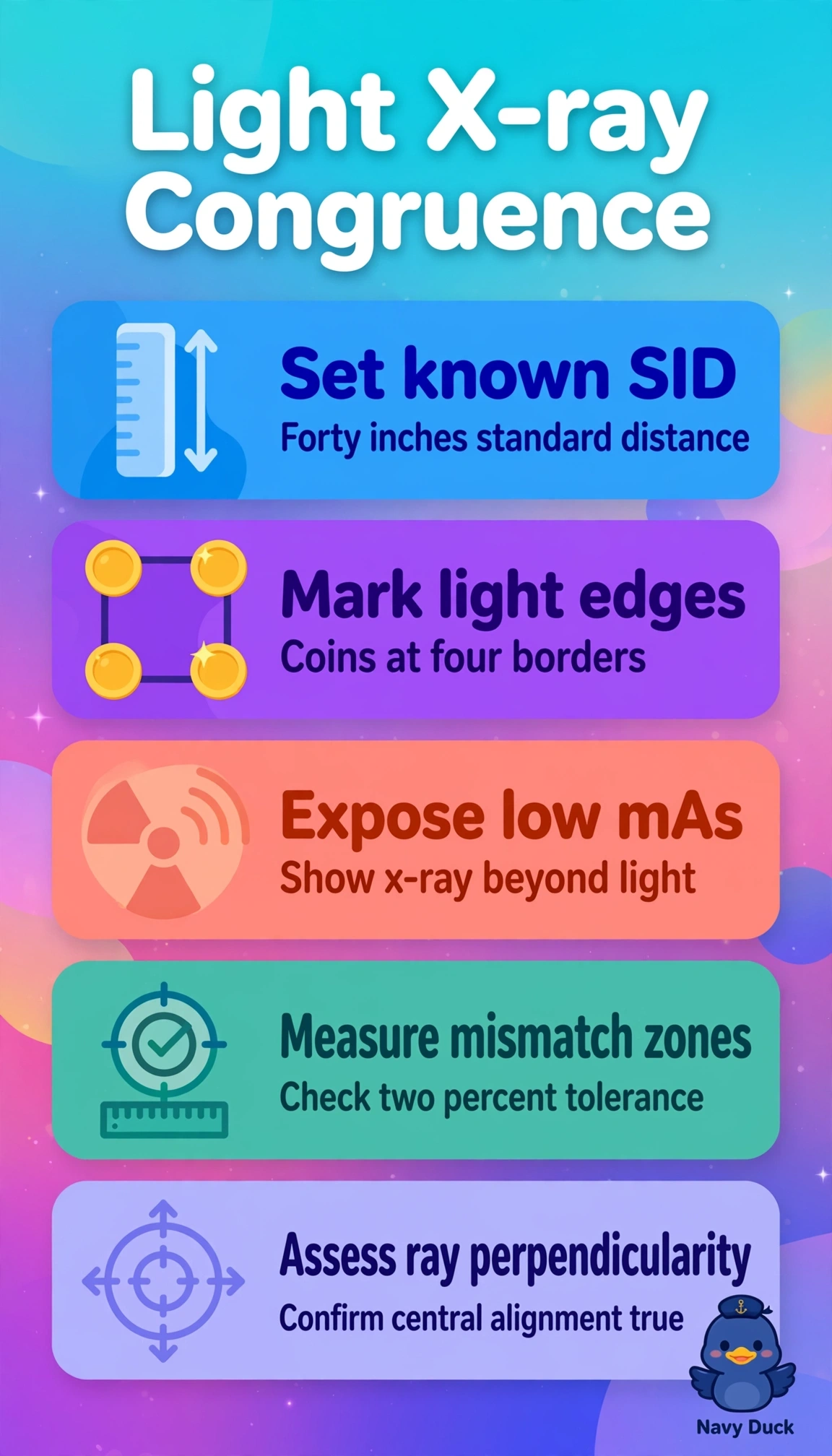
You’re checking whether the radiation beam matches the light field and stays properly aligned. Coins at the light-field edges reveal congruence because the exposed image shows where the x-ray field extends beyond the marked edges.
Full Explanation
Light-field-to-radiation-field congruence and central ray alignment testing verifies that the visible collimation matches the actual x-ray beam within tolerance, commonly within 2% of SID, and that the central ray is perpendicular to the receptor. This helps prevent unintended tissue irradiation or image cutoff. Placing radiopaque coins at the light-field borders on the cassette and making an exposure lets you measure any x-ray field extending beyond the coin shadows and assess beam alignment, directly testing the stated QC requirement. A wire mesh evaluates spatial distortion or linearity across the image receptor, not field congruence, so it addresses a different image-quality concern. A step wedge evaluates density or contrast differences and may help assess kilovoltage performance, but it does not test field alignment. A pinhole camera estimates effective focal spot size and sharpness, addressing tube performance rather than light-to-radiation congruence. Exam caveat: remember the commonly used 2%-of-SID limit and check all four field edges, not just one side. Practical check: at the 40-inch SID, set a known field size, mark the light-field edges with coins, expose at low mAs, and measure any mismatch on the processed image.