
A new fiber run between two campus buildings shows link-down on both switches. The transceivers match. A visual fault locator injected at the near transceiver's transmit position is visible at the far transceiver's transmit position. Which fault does that pattern indicate?
Select an answer to reveal the explanation.
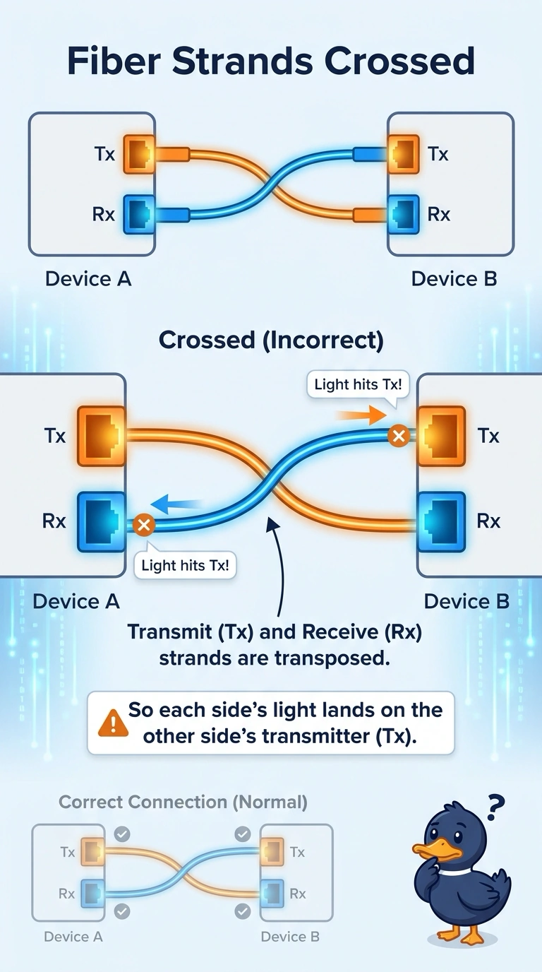
Short Explanation
Fiber is a one-way street on each strand. You send on one strand and listen on the other, and if both ends talk on the same strand, nobody is home to hear it. Seeing your test light on the far end's transmit port means the pair is rolled, while dirt or distance would only dim a light that arrived on the receive port.
Full Explanation
Each fiber transceiver transmits on one strand and receives on the other. A correct patch crosses the pair so one side's transmitter faces the other side's receiver. When a visual fault locator injected at the near transceiver's transmit position is visible at the far transceiver's transmit position, both ends are using the same strand to send, and the receive strand is the opposite one. The link stays down because neither receiver is looking at the other's light. That is a polarity, or TX/RX, transposition, and it is corrected by swapping the pair at exactly one end. A single-mode strand mated to a multimode transceiver is a real fault, but it is not what a light appearing on the wrong port proves, and the scenario already says the transceivers match. An exhausted optical budget and dirty connectors reduce received power. They do not move the light from the receive position to the transmit position. The light is arriving; it is arriving at the wrong element. Exam caveat: swap the pair at one end only. Swapping both ends restores the original, broken polarity. Operational check: after one swap, confirm each switch shows link-up and that the received optical level on both transceivers is inside the manufacturer's range.