
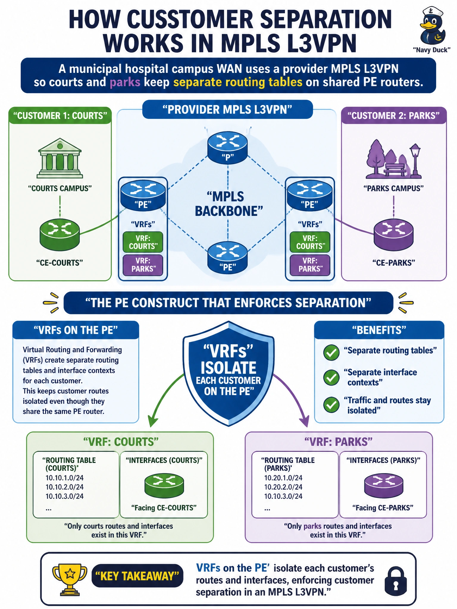
A municipal hospital campus WAN uses a provider MPLS L3VPN so courts and parks keep separate routing tables on shared PE routers. What PE construct primarily enforces that customer separation?
Select an answer to reveal the explanation.
Short Explanation
On the PE, VRFs are the separate waiting rooms: courts traffic and parks traffic do not share a routing table even though they sit on the same provider edge hardware.
Full Explanation
On a municipal hospital campus WAN using provider MPLS L3VPN so courts and parks keep separate routing tables on shared PE routers, the PE construct that primarily enforces that separation is the VRF. Each customer/agency gets a VRF that isolates its interfaces, RIB/FIB, and PE-CE routing from other VRFs on the same PE hardware. Combined with RD/RT and VPN labels across the core, VRFs are the local PE mechanism that keeps courts traffic out of the parks table and vice versa.
A single global routing table with CoPP classes named after each agency fails by concept. CoPP protects the control plane CPU; naming classes after agencies does not create separate routing tables or VPN isolation on the PE.
NHRP mappings that assign unique NBMA addresses per agency VLAN belong to DMVPN-style overlays, not to MPLS L3VPN PE VRF separation for courts versus parks.
BFD templates that drop parks packets whenever courts hellos are missing misuse failure detection as tenancy isolation. BFD does not provide per-customer routing-table separation on the PE.
Exam caveat: VRFs alone on one PE are VRF-Lite if no MPLS VPN backbone; with MP-BGP + MPLS they participate in L3VPN. Route targets control which remote VPN routes enter a VRF—still centered on VRF as the PE isolation container.
Operational check: show vrf / show ip route vrf COURTS versus PARKS on the PE; confirm interfaces are in the correct VRF; verify overlapping RFC1918 can exist in both without collision in the global table; ensure no unintended route-target import stitches the agencies together.